Cavitation and Flashing
Of the bad influences that there can be on control valves, one of the biggest that could be mentioned is cavitation and flashing. These phenomena cause noise and vibrations, which can cause damage to the valve body or nearby pipes, and can have a large effect on valve sizing.
In selecting a suitable valve, an adequate understanding of the effects of cavitation and flashing is needed.
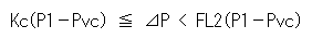
➔ Occurrence Mechanism / Pressure Loss and Pressure Recovery Conditions
◎ Occurrence Mechanism
■ Occurrence of Air Bubbles (Cavity)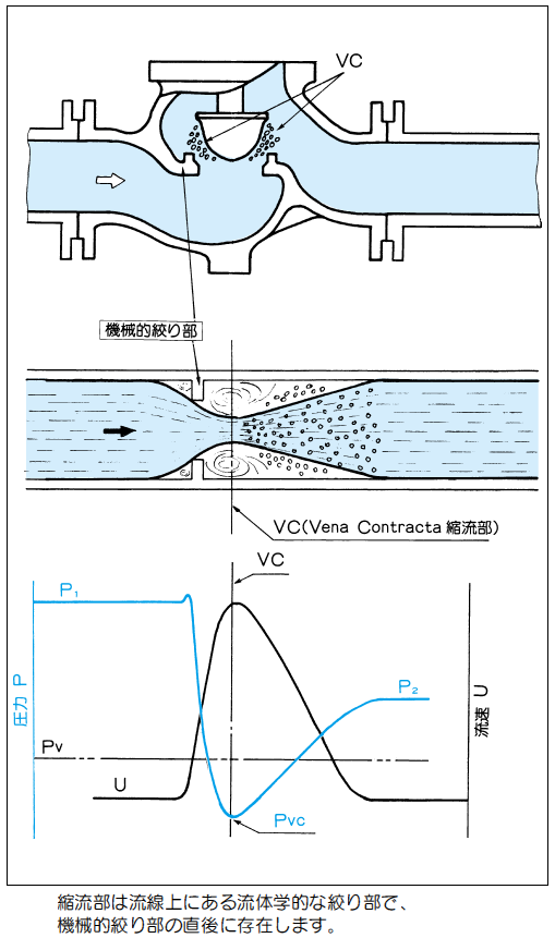
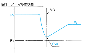
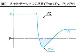
Immediately after a fluid passes through the valve sheet area, the flow velocity (U) reaches maximum, and the pressure (P) drops. (Figure at right)
If the fluid pressure falls below the vapor pressure (Pv), boiling starts and vapor air bubbles appear. In this case, the evaporation temperature rises, so that the boiling is not due to ordinary vapor occurrence, but to a drop in the fluid pressure due to the Pv.
■ Crushing of Air Bubbles (Cavitation)
When the pressure that had dropped due to transit of the valve starts to return to its normal level on the downstream side, the air bubbles are again compressed, and then crushed.
This sudden pressure-crushing of the air bubbles releases energy that is radiated to its surroundings, crashing against the valve body or the inner walls of the piping, causing severe mechanical damage. This collision force is believed to be as high as 700 MPa.
In such cases, noise can occur over a wide frequency range spanning 15 to 10000 Hz. The damage caused by this phenomenon is called Cavitation Erosion.
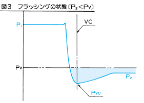
■ Change in Flow Volume due to Flashing
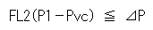
If the fluid pressure that fell below Pv during valve transit fails further downstream to rise back up to Pv, the exit side may enter a flashing condition.
A portion of the fluid turns to vapor, the specific volume increases, and flow clogging occurs, so that the flow volume transiting the valve is no longer proportionate to  , and a situation arises where, even if the differential pressure is increased, the flow volume will fail to increase.
◎ Pressure Loss and Pressure Recovery Conditions
The diagrams below shows the change in pressure when the fluid transits inside the valve, or in other words, the pressure loss and pressure recovery conditions.